





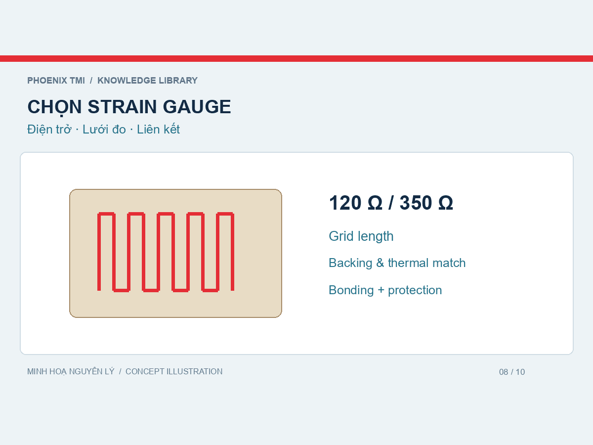
A resistance strain gauge converts local surface deformation into a resistance change. With a suitable bridge, excitation and acquisition system, this is converted to strain. Force requires an appropriate mechanical relationship or calibration; the gauge alone does not directly establish force.
Concept illustration prepared for Phoenix TMI; not measured data or a manufacturing drawing.
Resistance is only one selection parameter
Nominal resistance must suit the instrument and bridge, but gauges with the same resistance can differ in grid length, pattern, backing, thermal compensation and leads. Do not substitute a model solely because it is rated 120 or 350 ohms.
Parameter | Selection consideration |
|---|---|
Resistance | Instrument, bridge and excitation compatibility. |
Grid length | The surface region over which strain is averaged. |
Pattern | Measurement directions and single- or multi-axis requirements. |
Backing and thermal compensation | Substrate material and temperature environment. |
Backing size and leads | Bonding area, wiring and connection protection. |
A shorter grid is not always better
A strain concentration and a heterogeneous material present different measurement problems. Select gauge length for the object and purpose, considering spatial averaging rather than only the available bonding space.
Bonding adhesive and protective coating
The adhesive transfers strain into the gauge. A coating provides environmental protection according to its properties. Protective silicone is not automatically a strain-transferring adhesive, and a bonded gauge is not automatically ready for outdoor or wet exposure.
CN-E, CC-35, Extra 4000 and TSE397C must be selected against their own documentation, substrate, temperature, moisture and measurement duration. Their roles are not interchangeable simply because they appear in the same installation workflow.
Installation and channel checks
Define orientation and surface preparation.
Follow the adhesive system’s bonding pressure and cure instructions.
Provide strain relief and protect connections.
Check wiring, resistance, insulation and zero stability.
Retain the gauge factor, full model, batch and bridge settings.
Selecting a Showa model
The Showa strain gauge page brings documented models together for comparison. Supply the full model, substrate, strain and temperature range, test duration and readout information. Unconfirmed specifications should be checked, rather than inferred from a similar model.
References
This article explains principles and equipment selection. Perform testing to the required standard and equipment instructions.


