





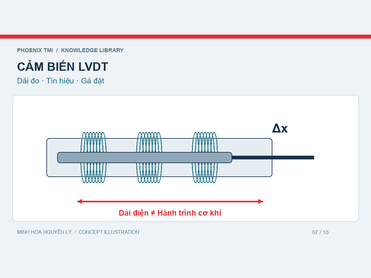
An LVDT measures displacement using a linear variable differential transformer. Movement of a core changes the relationship between coil signals; suitable conditioning converts that response into a displacement measurement.
Concept illustration prepared for Phoenix TMI; not measured data or a manufacturing drawing.
Look beyond the millimetre figure
A ±5 mm range and a 0–5 mm range describe different spans or reference conventions. Check the model’s origin, direction and specified electrical range. Mechanical travel may exceed the range over which the electrical performance is specified.
Question | Useful information |
|---|---|
What is measured? | Movement between points on a specimen, a machine mechanism or a reference frame. |
Which range? | Expected movement, starting position and travel allowance. |
Which signal? | AC LVDT with conditioning or a model with integrated electronics; check its data sheet. |
How is it mounted? | Probe arrangement, fixture, working travel and clearance. |
How is data collected? | Readout or DAQ compatibility, sampling and synchronization with force. |
Internal non-contact operation versus the probe
The electromagnetic coupling between core and coils does not require a sliding electrical contact. A contact-probe LVDT can still touch the specimen. Evaluate the actual probe construction rather than assuming the entire measurement is non-contact.
Define the measurement reference
A moving or flexible mount can introduce fixture and frame movement into the signal. Define the reference points and mounting arrangement for specimen deformation. Crosshead travel does not automatically represent local specimen displacement.
Check the complete measurement chain
Match the sensor, conditioner and acquisition channel against their specifications.
Verify direction, units, zero and scaling.
Check or calibrate the complete chain within the intended working range.
Retain sensor identification, mounting details and channel settings.
Discussing a configuration
For Phoenix TMI Delphius displacement sensors and Perseus acquisition, provide the range, mounting application, sensor output and existing equipment. A matching connector alone does not establish electrical compatibility.
References
This article explains principles and equipment selection. Perform testing to the required standard and equipment instructions.


